Published on 2023-12-13 in
Linux,
Software,
Windows
TCP/UDP hole punching or NAT traversal works as following:
A and B are behind NAT and want to communicate, while you have public relay server, S.
1. A connects to S, B connects to S
2. S send A ip and port to B, and send B ip and port to A
3. One of A or B try to connect to the other by the address S shared
Note1: For hole punching you don’t need uPnP IGD or port forwarding
Note2: UDP hole punching works more reliably than TCP hole punching as it’s connectionless by nature and don’t need SYN packet
Note3: Hole punching isn’t a reliable technique as router or other firewall may see B ip address is different from S ip address and block the inbound connection
Note4: STUN is a standard protocol that implement UDP hole punching although you can create a custom protocol as well following the above steps
Bryan Ford – Peer-to-Peer Communication Across Network Address Translators
Published on 2023-05-19 in
Linux
- Are you tired of entering your password for sshing into a remote server?
- Are you tired of verifying host fingerprint changes every time?
Use this golden ssh command and save your valuable time
ssh -o "StrictHostKeyChecking no" -i ~/Documents/identify root@ip
echo "y\n" | HOSTNAME=`hostname` ssh-keygen -t rsa -C "$HOSTNAME" -f "$HOME/.ssh/id_rsa" -P ""
# copy key to remote
ssh-copy-id userid@hostname
sshpass -p pass ssh root@ip
Published on 2023-05-19 in
Linux
You can use the @reboot keyword in crontab to start a shell script at system startup but here is why this isn’t a very good solution to do that.
The problem is that if you don’t shut down the system cleanly on the next startup this message will pop up and cron will simply skip over running your command.
"Skipping @reboot jobs -- not system startup"
The solution is easy, just use a systemd service.
/etc/systemd/system/service_name.service
------------------------------------------
[Unit]
Description=some description
After=network.target
StartLimitIntervalSec=0

[Service]
Type=simple
User=root
ExecStart=/home/user/script.sh

[Install]
WantedBy=multi-user.target
UnixDaemon – How Does Cron Reboot Work
Published on 2023-01-30 in
Linux
Regex, Sed, and AWK are freaks in programming but they are pretty simple, well not at the beginning though.
Here I summarize some of the most amazing ones for RegEx
- To Be or Not To Be, is possible with: LookAround
- Stop Worrying! Regex101 is all you need to know
Published on 2022-07-08 in
Linux
Here I list cool bash tricks I learned:
– Bash Heredoc
Published on 2022-05-06 in
Linux
Ok the title is a bit long but why google create such a nice debug interface and make it so difficult to access it.
1. open chrome with remote debug enabled
chromium --remote-debugging-port=9222 https://github.com/
2. Install websocat to create websocket to chrome
sudo pacman -S websocat
3. Find magic chrome ws url. To do that visit following url
http://127.0.0.1:9222/json/list
4. Connect to the websocket
websocat ws://127.0.0.1:9222/devtools/browser/<GUID>
5. Execute magic command. Here just scrolling the page
{"id": 1, "method": "Runtime.evaluate", "params": {"expression": "document.documentElement.scrollTop = 600"}}
Few Notes
- Websocket URL directly from chrome(stdout) don’t address any target page. Stick to
http://127.0.0.1:9222/json/list or see cdp tutorial for further information.
- For automated command execution in debug session you can use following scripting
chrome_loop.sh
inotifywait -q -m -e close_write cmd |
while read -r filename event; do
     cat cmd | websocat -n1 ws://127.0.0.1:9222/devtools/page/<GUID>
done
cmd
{"id": 1, "method": "Runtime.evaluate" , "params": {"expression": "alert('hi')"}}
The combination of FMCOMMS3 and PetaLinux is working only on Ubuntu 16.04 LTS, PetaLinux 2018.3, Vivado 2018.3
Required Packages:
sudo apt-get install -y gcc git make net-tools libncurses5-dev tftpd zlib1g-dev libssl-dev flex bison libselinux1 gnupg wget diffstat chrpath socat xterm autoconf libtool tar unzip texinfo zlib1g-dev gcc-multilib build-essential libsdl1.2-dev libglib2.0-dev zlib1g:i386 screen pax gzip
Installing PetaLinux
Create a new directory
sudo mkdir -m 755 PetaLinux
sudo chown bijan ./PetaLinux
Install PetaLinux by running the following command.
./petalinux-v2018.3-final-installer.run .
Building Vivado Project
Clone Analog Devices HDL repository
git clone https://github.com/analogdevicesinc/hdl.git
git clone https://github.com/analogdevicesinc/meta-adi.git
Make HDL Project
export PATH="$PATH:/mnt/hdd1/Vivado/Vivado/2018.3/bin"
make fmcomms2.zc702
Creating a New PetaLinux Project:
source ../settings.sh
petalinux-create --type project --template zynq --name fmcomms3_linux
Then change directory to the created project directory.
petalinux-config --get-hw-description=<hdf file directory>
set Subsystem AUTO Hardware Settings -> Advanced bootable
images storage setting -> u-boot env partition settings -> image
storage media -> primary sd
/home/bijan/Projects/ADI_Linux/meta-adi/meta-adi-core
/home/bijan/Projects/ADI_Linux/meta-adi/meta-adi-xilinx
Download following files and write it down to meta-adi/meta-adi-xilinx/recipes-bsp/device-tree/files
device-tree.bbappend
pl-delete-nodes-zynq-zc702-adv7511-ad9361-fmcomms2-3.dtsi
zynq-zc702-adv7511-ad9361-fmcomms2-3.dts
Build PetaLinux:
To build petalinux run following command inside petalinux directory
petalinux-build
In case of error remove -e from first line of system-user.dtsi file inside build/tmp/work/plnx_zynq7-xilinx-linux-gnueabi/device-tree/xilinx+gitAUTOINC+b7466bbeee-r0/system-user.dtsi
Program ZC-702 FPGA Board Through JTAG
Install Digilent Drivers
<Vivado Install Dir>/data/xicom/cable_drivers/lin64/install_script/install_drivers/install_drivers
To program the board using jtag interface. First we should package the kernel with the following command.
petalinux-package --boot --fsbl images/linux/zynq_fsbl.elf --fpga images/linux/system.bit --u-boot --force
Then login to the root account and run following commands.
petalinux-package --prebuilt --fpga images/linux/system.bit --force
petalinux-boot --jtag --prebuilt 3 -v
petalinux-boot --jtag --fpga --bitstream images/linux/system.bit
Program ZC-702 FPGA Board Through SD-Card
Enable SW16.3 & SW16.4 on ZC702 Board.
Generate BOOT.BIN file by executing following command:
petalinux-package --boot --fsbl images/linux/zynq_fsbl.elf --fpga images/linux/system.bit --u-boot --force
copy image.ub and BOOT.BIN to SD-Card
Customize Username and Password
To change username and password open
meta-adi/meta-adi-xilinx/recipes-core/images/petalinux-user-image.bbappend
Change analog to your desired password. If you want to remove login requirement comment EXTRA_USERS_PARAMS and enable debug-tweak in petalinux-config -c rootfs.
Change UART BaudRate
To change UART baudrate run
petalinux-config
go to Subsystem AUTO Hardware Settings -> Serial Settings -> System stdin/stdout baudrate
Useful Links
Analog Wiki – Building with Petalinux
Analog Wiki – HDL Releases
GitHub – Analog Device No OS
Published on 2017-05-27 in
Linux
One of the great feature of XInput is “Mouse Wheel Emulation” that I graceful with it for more than 5 years. Lately I notice it relieve my hand If I could trig wheel emulation by a key on keyboard instead of a mouse button.
Unfortunately up to this time Evdev not support that and pushing a mouse button through a synthetic way (like using bash script or liunx API) won’t trick EvDev. The reason behind this is that Evdev Wheel Emulation is a device specific driver. you won’t be able to enable it on all devices so it only executed if a button is pressed only on the specific device that you enable emulation on . Moreover after the triggering, wheel emulation only apply to movement of this specific devices with trigger. The figure below show two scenario that lead to unsuccessful wheel emulation.
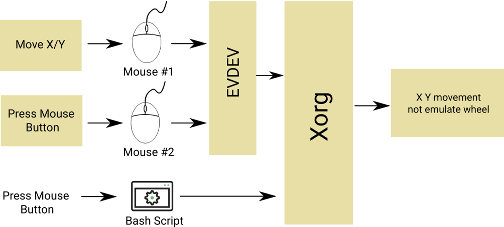
In a nutshell if you press mouse button source from a bash script emulation not work because EvDev driver won’t get it at all thus the button press have to come from a event-based device and not a complete virtual software. Additionally the movement and button press should come from same device. So as shown in the image, movement on Mouse #1 won’t do the emulation triggered from Mouse #2. To recap:
- The button press should come from an event-based device
- Trigger and movement should be on same device
Solution: Uinput-Mapper
Uinput is a kernel module to create event-based device. Uinput-Mapper is a wrapper around uinput in python that can create duplicate from a physical device and then manipulate it. Unfortunately python and Uinput-Mapper are slow and that can cause unexpected lag on mouse movement so the idea in here is to only use Uinput-Mapper under necessary cicumstances.
Uinput-Mapper can be cloned from this github repositories. If you get a glimpse of uinput-mapper, you notice two files input-read and input-create. input-read is a python script that read all event from a event-based device and spit all events out in form of pickle to stdout. For those who like me that don’t know what pickle is, pickle is a saving format. It can save and restore any type of variable so with power of pickle you can save a complex class and restor all variables and function in the state that it had been saved before.
Now what is input-create? input-create is twin of input-read that first create a event-base device and then get all event from stdin in form of pickle and then execut the events on a virtual device that has been just created by the script. To summerize input-read capture all events from an actual device and convert it to pickle, and then input create duplicate device and execute captured events coming from input-read.
So you had to pipeline all output of input read to input-create with something like command shown below
$ ./input-read -D /dev/input/event3 | ./input-create
The -D option in above command imply that input-read output is in format of pickle(not in a human readable format).
Keycode Based Shortcut Trigger
Now the time hase come to manipulate uinput-mapper to our requiment. I think posting all codes in here will clutter the post structure so I explain basic of modification applied on uinput-mapper and leave all codes to my github Bijoux repository.
First we need a script to trigger on pressing a key on keyboard. For sake of simplicity and because of my extra experience with bash I use bash over python to do the key detection and then used stdio to pass it to input-read. The big picture here is first using input-mapper we create a duplicate of our physical mouse. How? by running exact command mentioned above. Then we disable the physical mouse in XInput by running
$ xinput disable $MOUSE_ID
Now instead of data passing directly to EvDev, it pipelined through synthetic event-base device and then pass to EvDev. Here the trick is to write a script (we call it shortcut from now on) to detect a shortcut and then when a shortcut is detected we inject a synthetic event into virtual mouse that we have been created previously. Now from EvDev perspective, this won’t be any different from the event Physical Mouse #1 generate so it trigger the emulation wheel and moving in x/y direction actually scroll the screen on the active window. The figure below demostrate the forgoing concept.
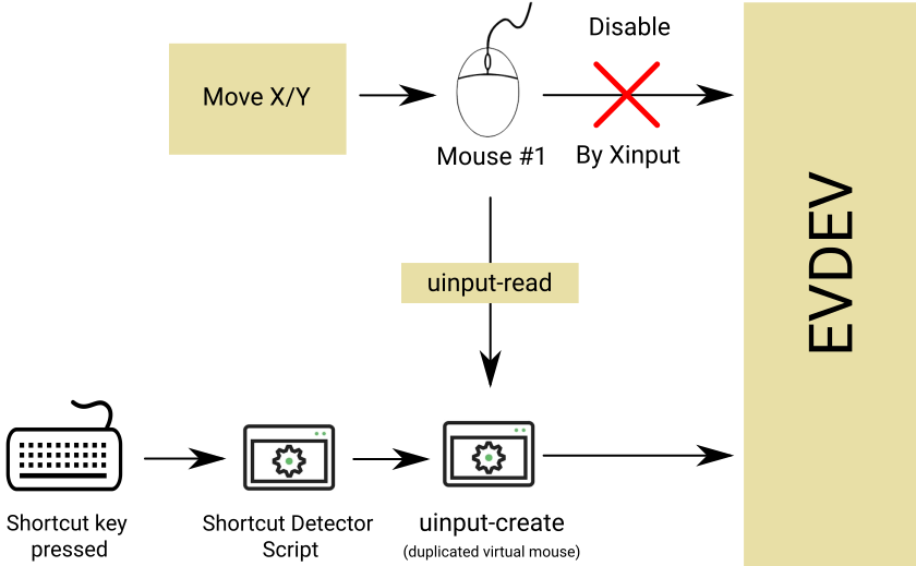
shortcut script detect a key press -> send a notification to input-read -> input-read load a previously recorded button press -> send recorded event to uinput-create -> uinput-create execute synthethic event as the same as other event come from mouse #1 -> …
Performance Issue
As remark previously, python scripts are slow intrinsically passing all mouse events through it cannot be accepted from performance point of view. Furthuremore in my brief test script runtime speed create not dramatic but noticable lag on mouse movement. To solve this issue bridge solution described above should only applied if and only if the wheel emulation should excute on that time. To do that following vivid shortcut (script) clears how this can be done.
The script is nothing more than a program than switch between physical mouse and virtual mouse on the fly. This is accomplished by using enable/disable function of XInput
#!/bin/bash
MOUSE_ID=($(xinput list | grep -m 1 MOUSE_MODEL | awk -F "=" '{print $2}' | awk -F " " '{print $1}'))
VIRTUAL_ID=14

while read -r line
do
    #echo $line
	if [ "$line" == "key press   108" ];then
		echo 1 #inform input-read
		xinput disable $MOUSE_ID
		xinput enable $VIRTUAL_ID
		while read -r line
		do
			if [ "$line" == "key release 108" ];then
				echo 0 #inform input-read
				xinput enable $MOUSE_ID
				xinput disable $VIRTUAL_ID
				break
			else
				break
			fi
		done < <(xinput test 12)
	fi
done < <(xinput test 12)
Published on 2017-03-03 in
Linux
To deploy qt application or harder QML app you need a tool called windeployqt availible in C:\Qt\Qt5.7.0\5.7\mingw53_32\bin or something like that. To get start open a cmd there and add QtBin path to your enviroment PATH variable.
$set PATH=%PATH%;C:\Qt\Qt5.7.0\5.7\mingw53_32\bin
run following
$windeployqt --qmldir I:\Home\Projects\AllegroAss\UI I:\Home\Projects\AllegroAss\Sources I:\Home\Projects\AllegroAss\Sources\release
Add some icon, spice (winpthread libgcc_s_dw2-1 and libstdc++-6) and you are done.
Published on 2017-02-03 in
Linux
First of all Microchip BM71 is the shittiest module I have ever seen in my life. The antenna gain is poor. Documentation is so bad that simple things are missing and maximum throughput is limited to 3KB/s with 10ms as minimum connection interval. You can find how I calculate the throughput by checking on this article about BLE specification. Here I assume you had the module. Already tried to communicate with it through UART and you failed to get any response back and now you are wondering why the module won’t reply.
The answer is quite simple, because the module is in the Transparent Mode. Transparent Mode is a state which all UART data sent to the module will simply sent out on bluetooth and no matter what you send in, the module wont respond you back. This state is sufficient if you want to send/receive data for simple tasks. But as soon as you need to change Device Name, TX Power or anything else you are stuck.
To get around this, In the Microchip way you have no way but to buy BM71 PICtail evaluation board. Although this should be simple and straightforward I don’t like how it sound. I mean ّI hate this marketing method that “Buy our evaluation board or you can’t use the module”. So here is a workaround to overcome this problem without access to PICtail.
Program BM71 Without PICtail EVM
My module is BM71BLES1FC2-0002AA which according to datasheet must use the PC tools ending with 0002AA. BM71 Module use IS1871 chip inside. It is a little confusing but inside IS1871 page there exist a Firmware & Software Tools v1.06 (matched to my model) that have all necessary tools to configure and update BM71 module firmware.
Now here if your customized board have a high performance uController on it you just need to create a shadow CDC device that get all data coming from USB and send it to BM71. So the all fancy PICtail EVM is nothing more than a “usb to serial (UART)” converter. you need a high performance uColntroller as if the conversion speed is not fast enough isupdate Firmware updateTool through error into your face as it did happen to me. In the case you face the same error as me you need to get knowing IS1870 chip better so you can write your own firmware update tool.
IS1871 Memory Map
IS1871 have 256 Kbytes embedded Flash memory that have all firmware and module configuration. The firmware is the software that operate module during normal operation and configuration is a part of firmware that indicate Device Name, TX Power and anything else that specified as a option in the datasheet.
The firmware start from address 0x0000 and end in 0x40000. The configuration start from 0x35000 and end in 0x37000 with 0x2000 as length. The module use a firmware called BLEDK3. To change the setting for module you have to first generate the configuration header and then write the generated file to the mentioned memory address. For header generation there exist a tool with name IS187x_102_BLEDK3_UI v100.123 inside UserInterfaceTool_V100_123 folder of Firmware & Software Tools v1.06 that you downloaded earlier.
If you need more detail on how to do this please feel free to leave a comment below.
Preparing For Writing To BM71
There are 3 steps you need to do before you able to write any data on BM71.
Step 1: Enter EEPROM Mode
There is a special mode that called eeprom mode (or programming mode). The first step is to enter eeprom mode that clearly explained in the manual and BM71 datasheet. in a few words, you need to set a special pin and while holding the pin at specified level, reset the module
Step 2: Connect To Module
After entering eeprom mode, the module stop the LED blinking (if you had one on your board). then you need to send 0x01, 0x05, 0x04, 0x0D, 0x00, 0x00, 0x00, 0x00, 0x00, 0x00, 0x00, 0x00, 0x00, 0x00, 0x00, 0x00, 0x00 I don’t know why this and what data they represent but sending out this will get the state machine to “CONNECTED” state. If the operation is successful you should get something from module (If you need to know the exact response feel free to ask)
Step 3: Erase The Flash
This step seems optional but it’s not. If you don’t send erase command before writing, any attempt to change memory will result in fail writing and memory won’t change. Again I don’t know why is module working this way or if I using it in a wrong way but I can’t write any register if I don’t send Erase command before to do so.
Secondly I don’t know where the erase command does actually erase. On my simple check this command only erase configuration area that I specified before and firmware remained unchanged but I’m not sure if it’s always the case.
To erase flash send 0x02, 0xFF, 0x0F, 0x0E, 0x00, 0x12, 0x01, 0x0A, 0x00, 0x03, 0x00, 0x00, 0x40, 0x03, 0x00, 0x00, 0x20, 0x00, 0x00 any response should indicate the erase operation is successful. I highly recommend to wait 1 second before sending any further command.
I noticed that the flash operation have some inside timeout watch dog. If the writing command execute later than this timeout any write attempt result in failure.
Step ∞: Disconnect
The last step after all read/write operation is disconnection. This option seems to be optional but highly recommended to execute. The disconnect packet is 0x01, 0x06, 0x04, 0x03, 0xFF, 0x0F, 0x00
BM71 Writing
To write a register we start with a base command template then fill it with appropriate value.
Write Template: 0x02, 0xFF, 0x0F, 0x0E, 0x00, 0x11, 0x01, 0x0A, 0x00, 0x03, 0x00, 0x00, 0x46, 0x03,0x00, 0x20, 0x00, 0x00, 0x00
packet_size = data_size + 19;
address = 0x35000;

write_temp[3] = 14 + data_size;//ACL
write_temp[5] = 0x11; //COMMAND=WRITE
write_temp[7] = 10 + data_size;//ISDAP
write_temp[15] = block_size;//LENGTH
memcpy(&write_temp[11],(uint8_t*) &address, sizeof(address));//ADDRESS
memcpy(&write_temp[19],(uint8_t*) (eeprom_table), data_size);//Data
The data_size is in byte. In above example I used data_size=16. On a successful write, BM71 return 0x02, 0xFF, 0x0F, 0x0E, 0x00, 0x10, 0x01, 0x0A, 0x00, 0x03, 0x00, 0x00, 0x46, 0x03,0x00, 0x20, 0x00, 0x00, 0x00 on a failure due to requirement for flash, the second to last 0x00 will changes to 0x01.

