Understanding the math behind length matching of each protocol is a key in reaching out a well designed PCB with a balance between performance and layout area and other manufacturing constraints. Unfortunately for some protocols such as SDIO these information remained under NDA’s and are confidential. Here I examined ZC702 reference design board and/or datasheet of the PHY chip or the ZYNQ UG933 for figuring out the knowledge behind the design.
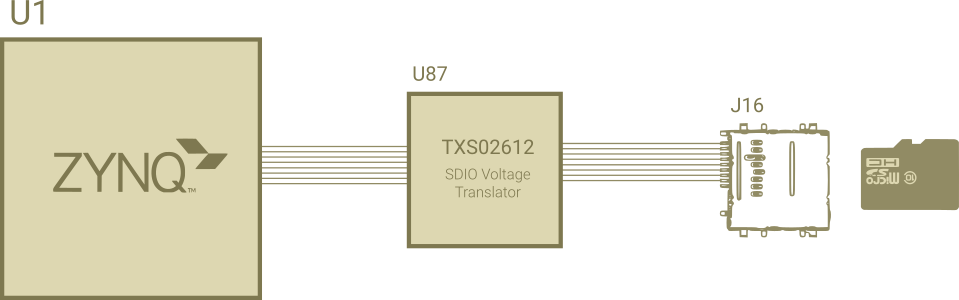
As I mentioned above, SDIO full specification isn’t at disposal of the public, nevertheless by examining the ZC702 traces delay and inspecting constraint manger of the board I finally grasp the situation. The ZC702 configuration simplified by the following diagram. Also under the diagram you can find out each traces delay, from ZYNQ AP-SoC chip to TI voltage translator and ended to SD Card connector. Delay for the CLK trace from U1 to U87 is a cummolative sum of U1 to R81 delay and R81 to U87, this is done by defining R81 ESpice model and creating an XNet in the Allegro SI Analysis.
From the SDIO specification, for proper High Speed Mode operation, the CLK line shoud be 1ns longer than CMD and DAT[0:3]. Furthuremore CMD and DAT[0:3] should reamin in a 50ps margin from each other which is a tight version of what UG933 recommended:
PCB and package delay skew for SD_DAT[0:3] and SD_CMD relative to SD_CLK
must be between 50–200 ps
But by inspecting following table which is extracted from ZC702 board you can conclude that all lines are matched together without any sign of 1ns delays on the CLK line.
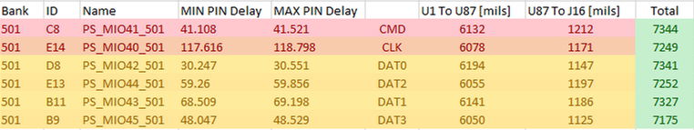
After checking out TXS02612 datasheet, you can see on page 12 the clock to channel skew is roughly around 1.5ns which can justify why the clk traces has the same length as other signals on the PCB.
The Reduced Gigabit Media Independent Interface or RGMII is an low pin count interface between the PHY chip and the controller. Ethernet protocol is instinctivly a Full-Duplex non-synced protocol, thus the TX and RX signals are completely independent. Differential traces from RJ45 back to the PHY chip are completely independent and only the phase matching in a differtial couple should be considered. For the RGMII signals, the mathing requirments is highly depends on version of RGMII that PHY chip supports. Here we assume a conformal with RGMII v2 without internal delays. In this case following traces in each group should length mathed to the margin of up to 100 ps with each other including ZYNQ package delay.
TX_DATA[0:3], TX_CTLRX_DATA[0:3], RX_CTLThe average delay of each group should be length mathched to corresponding CLK with a delay of 1.5ns shorter. MDIO and MDC are operating at max frequency of 2.5MHz thus doesn’t require any length mathing. Any other signal that does not mentioned can routed at any arbitary length.
Useful Links
Xilinx – AR# 59999: Design Advisory for Zynq-7000 SoC, eMMC – JEDEC standard
Texas Instruments – TXS02612: XS02612 SDIO Port Expander With Voltage-Level Translation
IEEE 802 – Specification Gaps and Improvement of MDC/ MDIO Interface


