Here I am, pursuing once more the old-fashioned machine learning. I’ll keep it short and write down useful links
The combination of FMCOMMS3 and PetaLinux is working only on Ubuntu 16.04 LTS, PetaLinux 2018.3, Vivado 2018.3
sudo apt-get install -y gcc git make net-tools libncurses5-dev tftpd zlib1g-dev libssl-dev flex bison libselinux1 gnupg wget diffstat chrpath socat xterm autoconf libtool tar unzip texinfo zlib1g-dev gcc-multilib build-essential libsdl1.2-dev libglib2.0-dev zlib1g:i386 screen pax gzip
Create a new directory
sudo mkdir -m 755 PetaLinux
sudo chown bijan ./PetaLinux
Install PetaLinux by running the following command.
./petalinux-v2018.3-final-installer.run .
Clone Analog Devices HDL repository
git clone https://github.com/analogdevicesinc/hdl.git
git clone https://github.com/analogdevicesinc/meta-adi.git
Make HDL Project
export PATH="$PATH:/mnt/hdd1/Vivado/Vivado/2018.3/bin"
make fmcomms2.zc702
source ../settings.sh
petalinux-create --type project --template zynq --name fmcomms3_linux
Then change directory to the created project directory.
petalinux-config --get-hw-description=<hdf file directory>
set Subsystem AUTO Hardware Settings -> Advanced bootable
images storage setting -> u-boot env partition settings -> image
storage media -> primary sd
/home/bijan/Projects/ADI_Linux/meta-adi/meta-adi-core
/home/bijan/Projects/ADI_Linux/meta-adi/meta-adi-xilinx
Download following files and write it down to meta-adi/meta-adi-xilinx/recipes-bsp/device-tree/files
pl-delete-nodes-zynq-zc702-adv7511-ad9361-fmcomms2-3.dtsi
zynq-zc702-adv7511-ad9361-fmcomms2-3.dts
To build petalinux run following command inside petalinux directory
petalinux-build
In case of error remove -e from first line of system-user.dtsi file inside build/tmp/work/plnx_zynq7-xilinx-linux-gnueabi/device-tree/xilinx+gitAUTOINC+b7466bbeee-r0/system-user.dtsi
Install Digilent Drivers
<Vivado Install Dir>/data/xicom/cable_drivers/lin64/install_script/install_drivers/install_drivers
To program the board using jtag interface. First we should package the kernel with the following command.
petalinux-package --boot --fsbl images/linux/zynq_fsbl.elf --fpga images/linux/system.bit --u-boot --force
Then login to the root account and run following commands.
petalinux-package --prebuilt --fpga images/linux/system.bit --force
petalinux-boot --jtag --prebuilt 3 -v
petalinux-boot --jtag --fpga --bitstream images/linux/system.bit
Enable SW16.3 & SW16.4 on ZC702 Board.
Generate BOOT.BIN file by executing following command:
petalinux-package --boot --fsbl images/linux/zynq_fsbl.elf --fpga images/linux/system.bit --u-boot --force
copy image.ub and BOOT.BIN to SD-Card
To change username and password open
meta-adi/meta-adi-xilinx/recipes-core/images/petalinux-user-image.bbappend
Change analog to your desired password. If you want to remove login requirement comment EXTRA_USERS_PARAMS and enable debug-tweak in petalinux-config -c rootfs.
To change UART baudrate run
petalinux-config
go to Subsystem AUTO Hardware Settings -> Serial Settings -> System stdin/stdout baudrate
Useful Links
Analog Wiki – Building with Petalinux
ADS has a broad way of aspects from IC design to the RF simulation, here we explore how to prepare your workspace to start layout phase after schematic design. ADS comes with tons of ready to use parts, these parts are available at <ADS>/ADS/oalibs/componentLib/. Here I demonstrate how to add and use RF_Passive_SMT library in your layout.
DesignKits>Unzip Design Kit...<ADS>/ADS/oalibs/componentLib/ and select library filebefore using the parts you need to setup the substrate file and technology file.
Options>Technology>Technology Setup.Referenced Libraries click on Add Referenced Library... button.ads_standard_layers and click on Ok button.Technology Setup dialogue and setup your substrate file based on ads_standard _layers that you imported earlierThe below image shows fooprint of ATC cap that inserted into layout.
To create footprint(artwork), you have two options:
1. create the layout by inserting rectangle, traces and etc into the board by using layout editor. In the reference links you can find link of an YouTube video demostrating that.
2. write an AEL script to create the artwork for you.
First option is easy, fast and works out of the box but it’s not scalable. writing down an AEL function is more clean from designer point of view. Fortunately Dr. Mühlhaus company wrote down a comprehensive guide (link down below) on how to create an Artwork based on AEL language.
Useful Links
YouTube – A vs B Modeling and Layout Footprint Generation
One of the great feature that comes along with ADS Package is the ability to create your design in a reverse flow. This necessity become more evident when you prefer to use other feature-reach layout tool than ADS and use ODB++ or ADFI tools afterward to import the design into the ADS for performing layout verification. In this tutorial I will summarize multitude of notes that you should consider to get a successful schematic back from your designed layout.
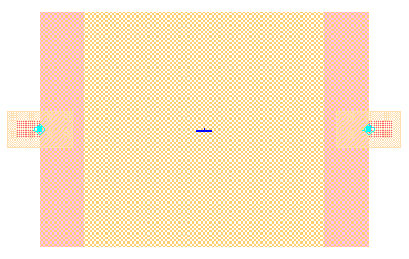
To start, first convert the traces into microstrip transmission line by right clicking on a trace and select Path/Trace > Convert Traces. If you were lucky the trace would change to microstrip type without any significance change in the trace color but if that’s not the case, you’ll notice changes in trace appearance like becoming invisible or transportation into a wrong layer. This is illustrated in Fig. 1 that shows a transformation nullify the line due to the fact that new wrong layer is an outline type. To solve the issue, proceed to the following steps. In case you hadn’t counter to the mentioned problem you can skip following steps abd generate schematic directly by Schematic > Generate/Update Schematic in the layout window.
Fig. 1. Transform the trace to microstrip will change the layer unwillingly
ADS sometimes have issues with ports and terms. So if you cannot generate schematic from the layout it is probably the main cause.
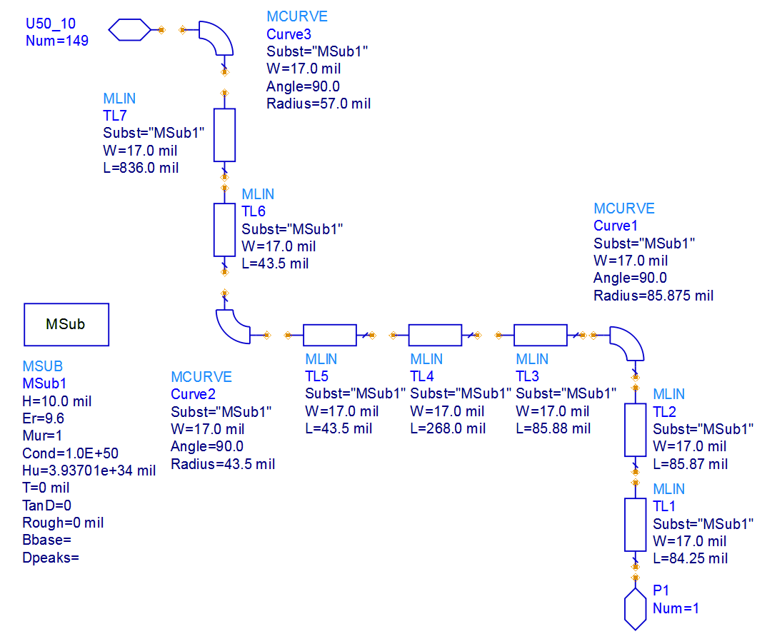
After generating schematic you’ll notice unconnected components placed vertically on the canvas. If you rearrange the components you get something like Fig 2 which by now you were recognized that ADS failed to import the connectivity back into the schematic. Unfortunately there is no automated fixation for this issue, which leaves you with no option but to make the connections manually. After that from the Parts panel, add a MSub component into the canvas. Now if you checkout files in your workspace you witness a new file named tech.subst. This file is a auto-generated stackup file that in many cases may contain some errors so it it recommended to to compare new generated substrate file with your current stackup and apply the required changes.
The last step is to configure the layer that microstrip will land on. To do so, double click on MSub component and adjust Cond1 parameter. Cond2 is, ADS said and I quote
Layer on which the air bridges will be draws
Probably the ground layer but still I have a doubt about that. Finally by selecting Layout > Generate/Update Layout in the schematic window regenerate the layout.
Cheers!
Understanding the math behind length matching of each protocol is a key in reaching out a well designed PCB with a balance between performance and layout area and other manufacturing constraints. Unfortunately for some protocols such as SDIO these information remained under NDA’s and are confidential. Here I examined ZC702 reference design board and/or datasheet of the PHY chip or the ZYNQ UG933 for figuring out the knowledge behind the design.
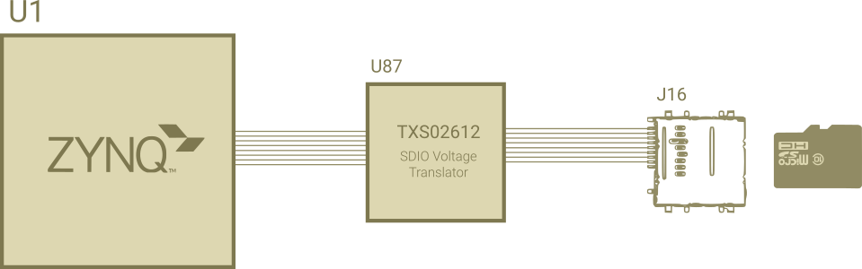
As I mentioned above, SDIO full specification isn’t at disposal of the public, nevertheless by examining the ZC702 traces delay and inspecting constraint manger of the board I finally grasp the situation. The ZC702 configuration simplified by the following diagram. Also under the diagram you can find out each traces delay, from ZYNQ AP-SoC chip to TI voltage translator and ended to SD Card connector. Delay for the CLK trace from U1 to U87 is a cummolative sum of U1 to R81 delay and R81 to U87, this is done by defining R81 ESpice model and creating an XNet in the Allegro SI Analysis.
From the SDIO specification, for proper High Speed Mode operation, the CLK line shoud be 1ns longer than CMD and DAT[0:3]. Furthuremore CMD and DAT[0:3] should reamin in a 50ps margin from each other which is a tight version of what UG933 recommended:
PCB and package delay skew for SD_DAT[0:3] and SD_CMD relative to SD_CLK
must be between 50–200 ps
But by inspecting following table which is extracted from ZC702 board you can conclude that all lines are matched together without any sign of 1ns delays on the CLK line.
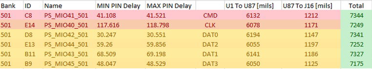
After checking out TXS02612 datasheet, you can see on page 12 the clock to channel skew is roughly around 1.5ns which can justify why the clk traces has the same length as other signals on the PCB.
The Reduced Gigabit Media Independent Interface or RGMII is an low pin count interface between the PHY chip and the controller. Ethernet protocol is instinctivly a Full-Duplex non-synced protocol, thus the TX and RX signals are completely independent. Differential traces from RJ45 back to the PHY chip are completely independent and only the phase matching in a differtial couple should be considered. For the RGMII signals, the mathing requirments is highly depends on version of RGMII that PHY chip supports. Here we assume a conformal with RGMII v2 without internal delays. In this case following traces in each group should length mathed to the margin of up to 100 ps with each other including ZYNQ package delay.
TX_DATA[0:3], TX_CTLRX_DATA[0:3], RX_CTLThe average delay of each group should be length mathched to corresponding CLK with a delay of 1.5ns shorter. MDIO and MDC are operating at max frequency of 2.5MHz thus doesn’t require any length mathing. Any other signal that does not mentioned can routed at any arbitary length.
Useful Links
Xilinx – AR# 59999: Design Advisory for Zynq-7000 SoC, eMMC – JEDEC standard
Texas Instruments – TXS02612: XS02612 SDIO Port Expander With Voltage-Level Translation
IEEE 802 – Specification Gaps and Improvement of MDC/ MDIO Interface
I know that there exist many disperse app note around how to export pin delay and why you should do that nevertheless I can’t find any comprehensive guide line which accompany you from A to Z of this process so I convinced to wrote down this post. For DDR3 and other sensitive high speed signals it is recommended to do the length matching with taking account package delay. This requirement only applied for non high-volume custom designed chips like Xilinx FPGA and other SoC’s available on market, in other word well-establish ICs like DDR chips pin delay’s had already been matched internally.
1. Open Vivado (my version is 2017.2)
2. On the TCL command window execute following commands
link_design -part xc7z020clg484-3
write_csv pin_delay.csv
Unfortunately output file of Vivado not work out of the box. You need to open the CSV file in some text editor (I use one of the most primitive one, Microsoft Excel) and remove the trivia rows and columns from it. Next thing is that Vivado export package delay in terms of Max Delay and Min Delay but Allegro only support Pin Delay. So you have to choose between the two or doing some math and get an average.
1. Remove all rows until only pins or banks remain without any empty row or heading
2. Remove all columns except Pin Name (like A9) and one of Max Delay or Min Delay
3. Add Unit. Vivado output delay in ps unit but allegro may not compromise with this choice. To overcome this issue, you need to add ps to the end of all delay values. In Microsoft Excel in a new column (we assume C is new column and delay values are in column B) write formula =B1&" ps"
4. get gripper from bottom corner of cell and drag it all the way down
5. copy column C and press Alt+E, S, V to paste special into B column. (I hate Excel, use bash+sed)
6. save file into a CSV file and open Allegro
1. Go to File > Import > Pin Delay, select CSV file and click on your chip.
2. Pick Import button and close the Pin Delay form.
Inserting via in RF and Microwave regions might seems to be a scary thing to do but as revealed through EM simulation for low portion of Microwave frequencies (below 10GHz) using a full via isn’t as worse as it seems to be. From “full via” I mean a via that start from top layer and end in bottom layer, using a partial via (that end or start on layers other than top or bottom) will results in considerable amount of reflection and poor S11.
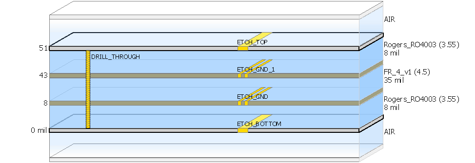
In order to find out a perfect transition from the top layer to the bottom layer , I use ADS Via Designer tool, to sweep on all available parameters. I ran parameter sweep on Drill Diameter, Anti-Pad diameter and pad size. I used a simplified stackup shown below which is a typical stackup in may RF boards, two layers of 8mils RO4003 substrate around a FR4 prepreg.
One of the main concerns regarding designing a perfect Via structure is being careful about return current path. In the case of my design, because I used GCPW (grounded coplanar waveguide) a rectangular via stitching may integrate more naturally to the board, albeit a two horizontal may work out too. On of the first concern in selecting right via stitching is distance of vias. Through long simulations I figure out that the perfect result will achieve when you place transition via stitching in the same position as the stitching vias you used to construct your GCPW.
In the following design with 17mils trace width and GND guard of 16 mils from each edge of transmission line, a via stitching with 100mils distance between center-to-center of via works the best.
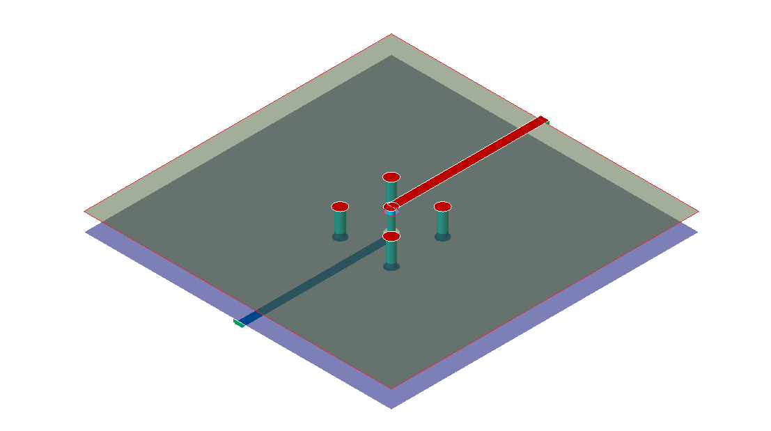
Note: dx and dy in ADS Via Designer are distances from the TL not from the corresponding via.
For the TL via, three degree of freedom are available but from manufacturing and physical point of view some of these values may not be practical. drill size is the most constrained parameter that restricted to both available bit size and the free space that is available on the board. After playing around these three parameters, it seems that no matter what value you choose for your drill size, there is always some pad size and anti-pad value that compensate drill size. For the pad size and anti-pad value you are limited only by the clearance value of your PCB manufacturer. For both of these value a step size of 1 mils seems to be fair. In my case I use a 0.3mm (12mils) drill size, and because of 4mils clearance the anti-pad diameter should be equal or bigger than 20mils.
After running a lengthy sweep on via ring size and antipad diameter, it revealed that at 0.3mm drill size, the via structure shows more inductance than capacitance. To reach a perfect wideband 50Ohm characteristic impedance, adding more capacitance to the structure was a must. In compliance with simulation results, best performance achieved when via ring is large enough and antipad is shorten to it’s minimum values. In my case the final choice was 0.3mm drill size, 27mm as the diameter of via pad and 8mils(min clearance)+12mils(drill size)=20mils for antipad diameter. The thicker green line at bottom is the S11 of chosen via.
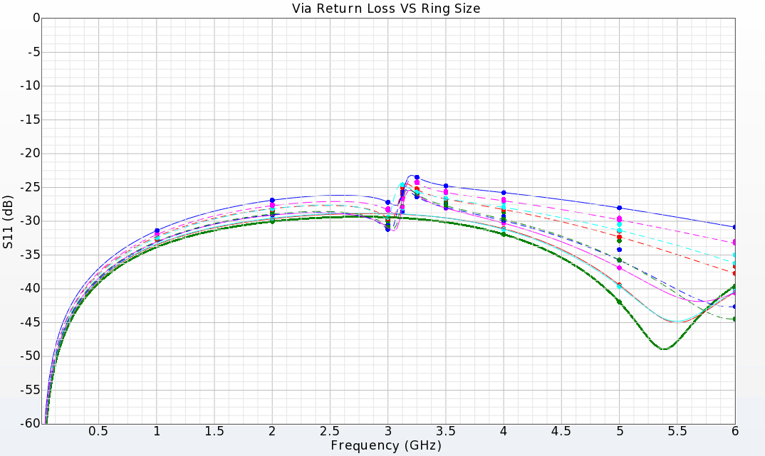
To conclude this post, we saw that at small drill sizes, DFM rules prevent to reach a decent performance. Small drill sizes results in higher inductance that need to be compensated by tight GND coupling and large via pad. To surpass this drill sizes can be choose to be bigger resulting in lower inductance and relieving capacitance requirement. Designing a via at low frequencies (sub 6GHz) isn’t a challenging problem but getting an invisible via from EM point, can be a big thumbs up work to do, moreover same rules and workflow can be applied at more critical frequencies to achieve better performances.
ADS Momentum is a full-wave EM field solver that merged with ADS package for more than 10 years. Starting with the ADS 2016.1, two new tools introduced by Keysight, the SI and PI Pro environment that can be accessed through layout interface inside the ADS software. In this post, I’ll talk about features of these two new tools and the reasons behind why they become an essential tool in the first place.
Momentum is a 3D EM solver. Have both RF and microwave options available. RF Mode solve EM fields in a simplified environment by utilizing approximated formulas while Microwave Mode use the full-blown Maxwell equations to solve the fields. Aside from accurate results that Momentum provide, this tools is memory and cpu-time hungry. If you try to simulate a simple two layer 6cmx6cm PCB with this tool, the process may take a day with consuming up to 80GB of memory to be solve. This is not a unexpected situation, because solving a board inside Momentum, make this tool to mesh all via, traces and planes in a full 3D environment. Momentum then solve the EM in a 3D box and calculate cross talk between all traces across the board even if they are completely isolated from each other.
In these cases if you don’t access to a superior machine, you will have to cutting out your design and simplify it as far as you could. This process is tedious and may take you further from achieving accurate results. This problem originated from not simplifying the design in a smart way and ignore the fact that we are surly simulating a PCB with focus on coupling and signal integrity. Thus far-field calculation is absolutely trivial.
To solve the discussed issue, Keysight developed a new EM solver engine that consider PCB requirement in mind. SI/PI Pro accelerate the simulating process 10 times by exploiting the special conditions that applied to PCB designs and RF boards that simplify the design. Although this simplification will results in less accurate simulation, it is a complete automated process with zero overhead and the boost in the simulation time is much greater than manual simplification that you can do in the Momentum.
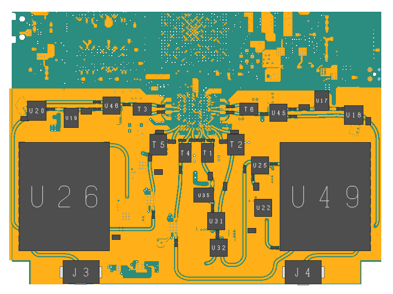
Fig 1. PNA6 pcb imported to ADS SI Pro
To evaluate the solvers, I imported PNA6 design into both Momentum and SI Pro environment. Then in momentum in order to cutback the cpu-time, I had to remove non-related layers, remove GND plane coppers and replace the layer with a slot plane, then optimize the Physical Model tab inside the EMPro options and finally remove superfluous traces from the layout. Carring out these preparation steps takes me almost 30 to 45 minutes which is quite long if you had to change the layout in Allegro and redo the whole process.
The simulation performed on 100MHz to 6GHz on a 4 layer RO4003 substrate. both Momentum RF and Momentum Microwave results in a same S-Parameter with slightly negligible differences in high frequency portion. The SI Pro results also compromises with Momentum although it shows some difficulty in achieving accurate S-Param the results are in complete compliance with momentum results and simulation process is so much faster than Momentum.
To conclude this discussion SI Pro shows a good fidelity toward achieving good results and as long as you can neglect 1 or 2dB errors the reults could be enough for you. Si Pro neither care for far field calculation nor can be used to simulate Antenna design but as far as your designs are limited to PCB or chip layout, SI Pro can serve as a nice companion toward reaching your goals in the product development process.
1. YouTube – Passive Circuit DesignGuide with a Momentum Simulation
2. YouTube – SIPro Introduction
Cadence and Keysight are collaborating with each other since 2000’s which brings one of unprecedented feature to reality, an ability to export your design from allegro to ADS seamlessly. In this tutorial I will demonstrate how to configure Allegro Design Flow Integration (ADFI) for Allgero 17.2 and ADS 2017 Update 1. I am aware that for ADSs prior to the 2016 version, there exists some compatibility issues with exporting from 17.2 version which is caused by some updates in Allegro SKILL engine, thus it is recommended to use the 2016 version or later.
To configure ADFI in Allegro you have two options, one, If you had installed Allegro alongside ADS on the same machine then you are already good to go, but if you have each software on a separate workstation you need to install Python 2 before going any further. I’m using 2.7 version and it works with Allegro 17.2 flawlessly. Follow these steps to configure ADFI:
File > ScriptChange Directory checkbox and open<ADS_FOLDER>\ial\scripts\eemLocalConfig.scrReplay button to run the scriptsetup and Restart the AllegroIf you did the steps correctly a item named Export To ADS/EMPro will show up in menu bar.
To export you need to select the nets of interest prior to export. To do that
Export To ADS/EMPro select Select Traces item.Cookie Cutter tab. In this tab you will create a board cutout geometry.Trace Select tab or be loosely wrap selected trace. This will be determined by the Initial shape slider. hull means exact shape and bounding box will be a loose surround.Expansion distance (I used 20 mils). This option expand the generated box with specified value.Build for Signal Net to generate the cookie cutter.Component/Pin Select tab and select the components of interest. select pins you wish to add ports in Selected Pins section.AutoPlace. Press OK button and exit the Select Geometry dialog.Export To ADS/EMPro select Export > Selected To ADS item.Save button.Before being able to import ADFI file to ADS you need to do these simple steps to get ADS ADFI import tool enable
Tools > App ManagerADFI Import ToolsFile > Import > DesignFile Type section select ADFI File Format from the list.OK button.1. Selecting the interested nets and creating ports in Allegro surly takes some time but the effort will payback in the simulation process (creating port in Allegro is much easier than in the ADS specially if you are dealing with a complex board)
2. After selection process saving the file WILL NOT save the selected nets. So if it take you too long to setup the board, don’t forget to save your work by using State > Save State in Export To ADS/EMPro menu bar
1. YouTube – ADS Data Link Basics (Part 1 of 3)
3. Dr. Muehlhaus -Momentum port: global ground or differential?
4. Virginia Tech – ADS Momentum Tutorial
I use AutoHotkey in almost all my application but I notice some Qt applications (Like ADS) had some difficulty interpreting the AHK keys correctly. The problem turns out to be affiliated with UAC and Admin rights rather than the Qt library. To solve the issue simply add following lines to the top of your AHK scripts that you want to be applied on the specific app.
#SingleInstance Force
SetWorkingDir %A_ScriptDir%
if not A_IsAdmin
   Run *RunAs "%A_ScriptFullPath%" ; Run Script as admin
This problem arises when you open a software instance with the admin rights while the AHK script doesn’t spawn with the same permission level. The above script simply run AHK with admin rights too so whether application is with or without admin right AHK script will always be able to set the key bindings.


